Together with the aerospace and automotive sectors, several sectors, including manufacturing and construction, also depend on welding as a fundamental operation. Since welded constructions guarantee both quality and uniformity as well as safety regulations, they have distinct welding needs. Standardized weld symbols help to facilitate communication in connection with welding. To adequately communicate with all relevant parties, a set of standardized symbols provides entire weld information, including dimension specifications. A good understanding of weld symbols reduces errors during construction, therefore preserving the required strength and design qualities of welded structures.
Weld symbols are a crucial component of engineered drawings and blueprints. By means of standardized symbols, the welding sector preserves a global communications system that facilitates welders’ and inspectors’ accurate understanding of instructions. Weld symbols remove obstacles that may otherwise result in poor and incorrect weld executions, therefore facilitating communication. To provide consistency between several production industries, standardized weld symbols originate from both the American Welding Society (AWS) and the International Organization for Standardization (ISO).
Understanding the Basics of Weld Symbols
Weld Symbol vs. Welding Symbol
Corporate welding communication relies on the welding symbol that shows specific weld directions via graphical features. The distinction between the weld symbol and the welding symbol needs proper recognition. Although it is part of a more comprehensive welding symbol, a weld symbol indicates the exact variety of weld types, including fillets between two surfaces, grooves joining three sides or plugs filling a hole. Combining weld symbols with other characteristics like dimensions and welding finishing kinds as well as additional symbols, a weld symbol serves as the entire notation format. The separate parts allow for avoiding misunderstandings, therefore shielding welding constructions from flaws.
Components of a Welding Symbol
A typical welding sign consists of multiple components. With all other elements placed relative to the horizontal line that forms the basis of the welding sign, the reference line indicates the precise location of the weld; the arrow ties the reference line to the joint to be welded. Additional information—such as the welding technique, specs, or other notes—can be included via the optional tail. The reference line carries the weld symbol itself to indicate the kind of weld to be done. Additional data such as dimensions, finishing requirements, and extra symbols indicate more instructions, such as weld contour and finishing procedures. These components, taken together, guarantee clarity in welding direction communication.
Positioning of Weld Symbols
The relative position of the weld symbol to the reference line tells where to put welds, either on the designated or opposite joint side. Weld placement should occur on the side of a joint pointed by the arrow when the weld symbol appears below the reference line. Anytime the weld symbol shows above the reference line, the weld location stays on the side opposite the reference line. When weld symbols are found on both sides of the reference line, welding criteria for both sides of the joint become required. This weld placement clarity convention helps prevent weld positioning mistakes during communication. Weld symbols need to be placed strategically for essential structural integrity objectives in bridge construction projects and pressure vessels, as well as high-rise buildings.
Common Types of Weld Symbols
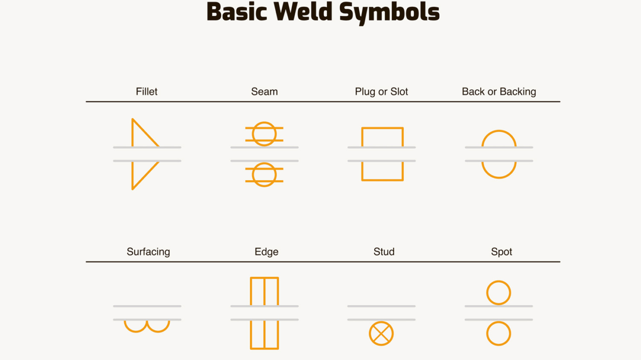
Fillet Weld Symbol
The symbol for fillet welds represents a triangular weld component, which works as a standard connection method between perpendicular-facing surfaces. Since it works well for joining flanges to webs inside I-beams, the symbol represents structural work. Weld leg size can be found to the left of the symbol, which shows a triangular right-angled shape.
The main reason fillet welds maintain their appeal as a weld type is their high bonding capabilities, together with their low requirement for preliminary work. Fillet welds show up in manufacturing for ships, cars, and heavy machinery as well.
Fillet welds are suitable for high-speed production environments because of their low preparation requirements and economy of cost. Careful weld execution reduces the development of welding faults such as undercutting and lack of fusion. Proper procedures during welding and accurate selection of filler materials are crucial to generate defect-free strong fillet welds.
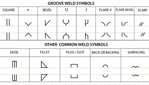
Groove Weld Symbol
Workpieces whose edges need preparation should use a groove shape created by a groove weld symbol. Five main characteristics define grooves used in welding: square, V, bevel, U, and J. For applications including pipeline construction and pressure vessel installations, the groove weld type is essential. Groove symbols use distinct graphical signs to depict different groove forms, including the V-groove, which is symbolized with a V. One can define both preparation depth and groove angle and root opening. Deep penetration is required for high-strength joints in atomic and gas pipeline infrastructure as well as structural steel frames; thus, groove welds are pretty significant.
Good edge preparation is crucial when doing groove welds since it guarantees thorough penetration into the base material. Defects resulting from inadequate preparation work reduce the strength of a weld. Using backing bars or root passes will help the welder achieve complete fusion and penetration during groove weld application.
Plug or Slot Weld Symbol
Plug or slot weld symbols are cylindrical or oval welds that pass through holes in one connection element to bond another aspect. The welding method is regularly used in lap connections that bind holes in one material with a solid piece of another. While dimensions inside the sign provide weld specs about space and measures between welds, the symbol for a plug or slot shows a circular or rectangular shape. Plug welds utilized with slots find extensive application in the automobile and space travel industries because they offer lightweight, lasting connections.
A typical application of these welds arises in situations where fillet or groove welds would not be suitable. Factors including welding parameter levels, material dimensions, and hole size determine the plug and slot weld strength. Weld success depends on the weld metal forming a strong connection by correctly uniting with the base material.
Spot Weld Symbol
Under resistance welding guidelines, the spot weld symbol shows a weld carried out at one location. Industry experts in sheet metal manufacturing and the automotive sectors use this symbol regularly. One circle shows the sign to indicate spot welds and offers guidelines for the pitch measurement between consecutive spot welds and the spot weld count. In manufacturing facilities, which generate strong connections for automobile body assembly and appliance production, spot welding is the primary method for speedy and effective metal sheet joining.
The main benefits of spot welds emerge from their rapid application process while preserving the base material’s structure. By carefully controlling the correct electrode pressure in tandem with current management, spatter generation and weld failure avoidance during the welding process are avoided. Applications of automated robotic welding systems enable accuracy through spot welding while manufacturing on an industrial scale.
Seam Weld Symbol
The seam weld symbol shows an uninterrupted weld connection created chiefly through resistance seam welding operations. The emblem allows manufacturers to develop leak-proof joints within tanks, as well as produce pipes and tubing. The symbol takes the shape of a straight line, which requires both length and pitch measurements based on user requirements. The production of fuel tanks, together with heat exchangers and waterproof enclosures, highly depends on the seam welding process.
A continuous joint produced through seam welding makes it ideal for situations that need fully watertight or airtight seam connections. Both electrode design and correct welding parameter management remain essential for producing welds that are uniform and have low defect visibility. Ramifications of laser seam welding exist because this technology serves manufacturing applications requiring precise and repeatable results.
Conclusion
The understanding of weld symbols makes it possible to achieve high-quality, precise welding results in manufacturing operations. These standardized symbols function as a global operational code that helps maintain work systems free from errors while ensuring system reliability and operational speed. Welders, along with engineers, can collaborate easily due to their ability to interpret these symbols for producing welds that fulfil standards and requirements. Weld symbols serve critical functions because structural integrity matters in all industrial settings. The commitment to welding standards, along with the professional’s understanding of symbols, enables them to deliver welds that are both safe and durable for different structures and products.